

Analysis on the Application of Film Capacitors in Electromagnetic Heating Equipment
- Categories:Industry news
- Author:
- Origin:
- Time of issue:2021-02-20 17:24
- Views:
(Summary description)Analysis on the Application of Film Capacitors in Electromagnetic Heating Equipment

Analysis on the Application of Film Capacitors in Electromagnetic Heating Equipment
(Summary description)Analysis on the Application of Film Capacitors in Electromagnetic Heating Equipment
- Categories:Industry news
- Author:
- Origin:
- Time of issue:2021-02-20 17:24
- Views:
Electromagnetic heating equipment converts power frequency alternating current or pure direct current into high-frequency alternating current (1KHz-1MHz) through half-bridge/full-bridge inverter technology. High-frequency alternating current will generate high-frequency alternating magnetic field after passing through various inductive loads When a metal object is in a high-frequency alternating magnetic field, the metal molecules will produce countless small eddy currents. The eddy currents cause the metal molecules to move randomly at high speeds, and the metal molecules collide and rub against each other to generate heat energy, and finally achieve the purpose of converting electrical energy into heat energy. Electromagnetic heating equipment is frequently used in our work and life. For example, household induction cooker/induction tea stove, commercial induction cooker, high-frequency hardening machine, sealing machine, industrial melting furnace, etc. This article uses three-phase high-power commercial induction cooker as For example, analyze the application of film capacitors in electromagnetic heating equipment.
Three-phase full-bridge circuit topology diagram of commercial induction cooker
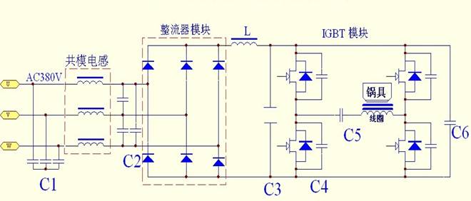
C1—C6 function description
C1/C2: Three-phase AC input filter, ripple absorption, improve the equipment's ability to resist grid interference
C1, C2 and the three-phase common mode inductor form a Pi-type filter, which plays the role of electromagnetic interference suppression and absorption in the equipment. On the one hand, the circuit suppresses the electromagnetic interference generated by the IGBT due to high-speed switching and is transmitted to the three-phase power frequency grid through the power line It affects the normal use of other grid-connected equipment. On the other hand, it prevents electromagnetic interference signals generated by other equipment in the same grid from being transmitted to the three-phase power frequency grid through the power line, affecting the normal use of the electromagnetic heating equipment itself. (Internal suppression) Interference generated by itself, external resistance to interference generated by other equipment, with double-sided) EMC=EMI+EMS
In actual use, C1 can choose MKP-X2 type (fixed capacitor for electromagnetic interference suppression), the capacity range is between 3µF-10µF, and the rated voltage is 275V.AC-300V.AC. Y-type connection is adopted, and the common terminal is suspended Not grounded. C2 can choose MKP type metallized film capacitor, the capacity range is between 3µF-10µF, the rated voltage is 450V.AC-500V.AC, and the delta connection is adopted.
In principle, the larger the capacitance selected for C1 and C2, the better the suppression and absorption of electromagnetic interference. However, the larger the capacitance, the greater the reactive current when the device is in standby. The withstand voltage should be based on the area where the device is used. It is reasonable to reserve a certain margin to prevent the voltage breakdown of the capacitor or the life of the capacitor when the power consumption is very small at night.
C3: Smoothing and filtering after rectification, DC-Link, absorbing ripple and completing the circuit of AC component.
C3 and choke coil L form an LC circuit, which converts the pulsating direct current after the three-phase bridge rectification into a smooth direct current for the subsequent inverter bridge and load. In the actual circuit of the commercial induction cooker core, C3 is generally composed of It is composed of film capacitors of tens of microfarads. The film capacitor at this position actually plays a role of DC support (DC-LINK), which is responsible for the absorption of ripple and the completion of the AC component loop, rather than what many people think (filtering) The capacitance of tens of microfarads, for a load of tens of kilowatts, the filtering effect is very small, and the voltage waveform of the DC bus cannot be smoothed at all. Due to the high-speed switching of the IGBT, it will produce A large number of high-order harmonic currents and peak harmonic voltages. If there is no capacitor as the absorption of harmonic currents and peak voltages, then the DC bus circuit will produce a large number of self-excited oscillations, which will affect the safe use of IGBTs, etc. and shorten the life time. Therefore. The use of film capacitors as a DC bus ripple voltage and ripple current absorption is currently one of the most commonly used methods at home and abroad.
In principle, the larger the capacitance selected for C3, the better the absorption effect. However, it should be noted that the capacitance is too large, which will easily cause the rectifier bridge when the device is just closed and powered on due to the excessive instantaneous charging current of the capacitor. Fuse and other overcurrent breakdown. In commercial induction cooker cores, the general selection principle is: half-bridge solution (1.5μF/KW) full-bridge solution (1.2μF/KW). This configuration is based on the conventional film capacitor energy It is inferred from the design process of 2A/µF.
For example, for a commercial induction cooker with a half-bridge 20KW model, the required C3 capacity is 20*1.5=30µF. The total ripple current of C3 is 30*2=60A for a full-bridge 20KW model, and the required C3 capacity is 20*1.2=24µF (actually 25-30µF is acceptable) The total ripple current of C3 is 25*2=50A. It is recommended that the actual selected capacitance and the allowable ripple current value of the capacitor should not be lower than the recommended value above.
The position of C3 must consider whether the ripple current value actually required by the circuit is less than the total ripple current value that the selected film capacitor can withstand (still a certain current margin), otherwise, if the circuit requires a ripple current of 60A, and The selected capacitor can withstand a total ripple current of only 40A, which will cause serious heating of the film capacitor, long-term overheating operation, greatly reducing the service life of the film capacitor, and severely causing the film capacitor to expand and bulge, or even catch fire. In terms of pressure resistance, general Select the rated voltage as 800-1000V.DC.
C4: IGBT peak voltage/current absorption, buffering and suppression to prevent IGBT breakdown
C4 is used as the turn-on/turn-off spike absorption of the IGBT. It is generally connected with the C-type or RC-type connection and is connected to the CE terminal of the IGBT. The withstand voltage is generally selected according to the rated voltage of the IGBT, and a certain voltage margin is reserved. In terms of capacitance, it can generally be between 0.01µF and 0.033µF. The most suitable capacitance should be selected according to the matching situation between the circuit and the IGBT. The capacitor at the C4 position must be used with a larger dv/dt value. Pay attention to whether the temperature rise is within the allowable range. If you use the RC type connection, you need to pay attention to the huge heat generation of R. When laying out, you need to keep a certain distance between R and C to prevent the capacitor from excessive heat radiation.
C5: Resonant capacitor, which cooperates with the load (inductance coil, transformer, etc.) to form an LC resonant circuit.
C5 acts as a resonant capacitor and forms an LC resonant circuit with L to deliver power. In use, pay attention to whether the rated voltage of the selected capacitor is sufficient (resonant voltage and equipment power, load material, magnetic load rate, distance from load to inductance, Circuit Q value, etc.). If the selected capacitor rated voltage value is lower than the actual resonant voltage value, then the capacitor voltage breakdown is likely to occur. In terms of current selection of the resonant capacitor, it is best to calculate the theoretical value first, and then make a preliminary selection The current value, after the equipment function meets the requirements, let the equipment be adjusted by measuring the actual value of the peak current/root mean square value of the LC circuit at the maximum power. If the actual high frequency current value passed is higher than the rated value of the capacitor If the current value is large, it will cause the resonant capacitor to overheat and run, and it will be prone to bulging or blow up or even fire after long-term work. The resonant frequency of the circuit should also be within the allowable frequency range of the resonant capacitor.
C6: DC bus absorption capacitor, local absorption, buffer and suppression of the peak voltage generated when IGBT switching.
C6 and C3 are also connected in parallel to the positive and negative poles of the DC bus. However, due to factors such as structure and wiring loops, the back-end IGBT is far away from the C3 capacitor, so it is necessary to directly lock a bus at the power end of the back-end IGBT module Absorb the capacitor and absorb the ripple voltage and ripple current generated by the IGBT locally. When C6 is selected, the withstand voltage is generally selected according to the rated voltage of the IGBT. Try to choose a large ripple current, large dv/dt, and stray inductance Small bus absorbing capacitance. For example, MKPH-S 0.47µF 1µF 1.5µF 2µF and other models, rated voltage 1200V.DC absorbing capacitor.
Common problems in the selection of film capacitors
A improper selection of rated voltage
The rated voltage is improperly selected, and the most frequent place is the resonant circuit part (C5). R&D personnel should base on the equipment's rated power, input voltage, circuit topology, inverter control method, load material, load magnetic load rate, circuit Q value and other parameters Make preliminary calculations after comprehensive consideration. After the prototype meets the requirements initially, you need to use an oscilloscope to add a high-voltage voltage probe to actually measure the peak-to-peak voltage, peak voltage, and root mean square voltage across the resonant capacitor when the device is at maximum power. Parameters such as resonant frequency are used to determine whether the selected resonant capacitor model and parameters are correct.
B. Improper selection of rated current
The rated current is improperly selected, and the most frequent occurrences are C3 (DC support) and C5 (resonance). If the actual current value required is greater than the allowable current value of the capacitor, it will cause the capacitor to generate serious heat and long-term high temperature operation, resulting in The life of the capacitor is greatly reduced, and it will blow up or even catch fire. In the equipment development, you can use a dedicated current probe or other methods to measure the actual peak current and the root mean square current, and then adjust the parameters of the capacitor. Finally, the temperature rise of the capacitor can be measured in the full power aging test of the equipment, and the selection of the capacitor can be determined according to the allowable parameters of the temperature rise of the capacitor. (Comprehensive evaluation of current measurement and temperature rise)
C improper wiring
The improper wiring method mainly occurs in the use of multiple capacitors in parallel. Due to the wiring method, the inconsistent wiring distance and other factors, each parallel capacitor is inconsistent in the circuit. It is finally reflected in the multiple parallel capacitors, and the temperature of each capacitor The rise is inconsistent. The temperature of the capacitors in individual locations is too high and burned. Therefore, it is necessary to connect and connect the capacitors in parallel, and try to achieve current sharing and improve the service life of the capacitors.
Waveform reference in the use of film capacitors
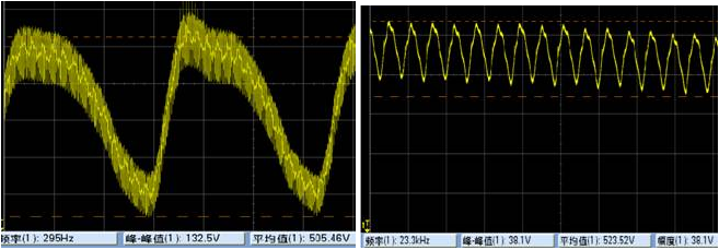
C3 voltage fundamental wave waveform (505V/300HZ) C3 ripple voltage waveform (38V/23.3KHz)
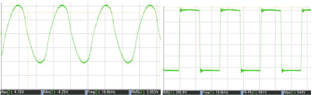
C5 resonance current waveform (Ip=84A Irms=60A) C4 absorption capacitor waveform (Vce=581V F=19.6KHz)
To sum up
The application field of electromagnetic heating equipment is increasing, and the use requirements and electrical performance parameters of film capacitors are getting higher and higher. This article uses a three-phase full-bridge commercial induction cooker as a case to analyze the role and function of film capacitors at various positions inside the equipment. The selection principles, precautions, etc., hope to bring some convenience to the majority of R&D personnel!
What's new
Time of issue : 2021-02-20
Time of issue : 2021-02-20
Time of issue : 2021-02-20
Time of issue : 2021-02-20
Contact us
TEL: +86-0757-28378933 / +86-0757-28378169
FAX: 0757-28370050 / 28378928
Email: cge@cgegd.com
Add: No. 7, Xinyou East Road, Ronggui High-tech Zone, Shunde District, Foshan City, Guangdong Province

Copyright © 2021 FOSHAN SHUNDE CHUANGGE ELECTRONIC INDUSTRIAL CO., LTD. 粤ICP备15046523号 Enterprise mailbox entrance